Power Factor Correction (PFC) Explained: The Key to Higher Power Utilization Efficiency | ARCH
As energy regulations tighten and industrial systems become increasingly digitized, the challenge of improving energy efficiency while maintaining system stability has become a critical concern in power supply design. Power Factor Correction (PFC) is one of the key technologies for achieving high power utilization efficiency and stable power systems. Learn from ARCH power supply blog articles on AC-DC design, EMC, safety standards and application tips that help engineers choose reliable power modules faster.

Power Factor Correction (PFC) Explained: The Key to Higher Power Utilization Efficiency
As energy regulations tighten and industrial systems become increasingly digitized, the challenge of improving energy efficiency while maintaining system stability has become a critical concern in power supply design. Power Factor Correction (PFC) is one of the key technologies for achieving high power utilization efficiency and stable power systems.
What Is Power Factor Correction (PFC)?
PFC, or Power Factor Correction, is a power electronics technique used to optimize the efficiency of AC input power. Its goal is to align the current waveform drawn from the power grid with the voltage waveform, thereby reducing reactive power and harmonic distortion.
In an ideal scenario, the current and voltage waveforms are perfectly in phase, resulting in a power factor of 1, meaning maximum energy efficiency. However, many electronic devices—especially those with rectifiers or switch-mode power supplies—distort the current waveform, leading to:
- Low power factor
- Non-sinusoidal input current
- High harmonic distortion, which can interfere with other devices
Integrating PFC circuitry can effectively correct these issues, improving overall system efficiency and operational stability.
Why Is PFC Necessary?
Without PFC, devices draw distorted and intermittent current from the AC mains, resulting in significant reactive power and total harmonic distortion (THD). This causes several negative effects:
- Reduced energy efficiency
- Higher load on system wiring and transformers, raising overall costs
- Mains pollution that affects grid quality
- reater risk of EMI interference with nearby equipment
These problems not only compromise the device’s own performance but may also degrade power quality across an entire facility.
Two Types of PFC
- Passive PFCo Uses inductors and capacitors to improve the power factoro Simple structure, lower costo Bulkier and less efficient; typically used in low-power applications
- Active PFCo Uses controllers and switching components to dynamically shape input currento High efficiency, compact size, power factor up to 0.95–0.99o The mainstream solution for medium- to high-power applications such as industrial automation, EV chargers, and telecom systems
Regulations Driving PFC Adoption
Most countries and regions have regulations governing power factor requirements. For instance, EN 61000-3-2 in the European Union mandates that electronic equipment exceeding a certain power threshold must integrate PFC circuitry to limit harmonic emissions.
Devices with well-implemented PFC are more likely to pass the following standards and certifications:
- EMC regulations (EN 55032 / CISPR32)
- International energy efficiency and EMC standards
- CB, UL, CE safety certifications
Four System-Level Benefits of PFC
- Four System-Level Benefits of PFC
A higher power factor translates to lower power losses—supporting ESG and sustainability goals. - Lowers Wiring and Transformer Costs
Smoother input current reduces thermal load on cables and transformers, simplifying heat management and reducing material costs. - Improves Grid Quality and Reduces Equipment Interference
Minimizing THD and EMI ensures stable operation and prevents disruptions to nearby systems. - Accelerates Certification and Market Launch
PFC compliance helps meet regulatory standards and speeds up product time-to-market.
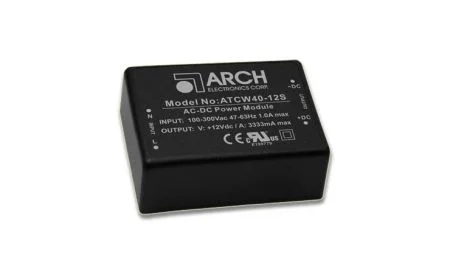
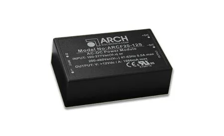
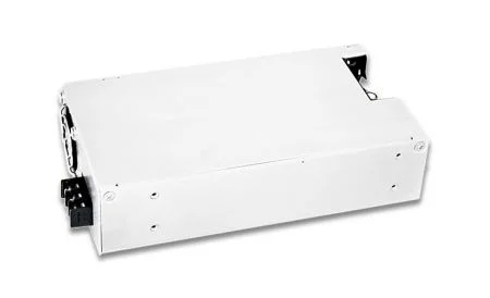
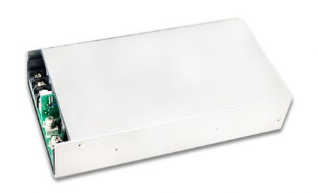
PFC in ARCH Switching Power Supplies
ARCH Electronics integrates active PFC into many of its medium- and high-power AC-DC switching power supplies, offering the following advantages:
- Wide input voltage range with power factor >0.95
- EMC performance compliant with EN 55032 Class B
- Certified to CB, UL, CE standards
- Supports 90–264VAC input, suitable for global deployment
Target applications include industrial control systems, instrumentation, energy management systems, and EV charging modules.
Conclusion: Choose the Right PFC Solution for a More Efficient System
Although not always the most talked-about technology, PFC plays a foundational role in improving system efficiency, meeting global compliance standards, and extending equipment lifespan. From low-power IoT devices to high-wattage industrial systems, implementing the right PFC strategy is key to building efficient, safe, and future-ready power solutions.
Additional Resources & Product Recommendations:
- Related Products
Power Factor Correction (PFC) Explained: The Key to Higher Power Utilization Efficiency | ARCH
The ARCH power supply blog shares practical guides on AC/DC design, EMC, safety approvals and thermal performance for real-world industrial and medical projects.
Each article is written for hardware engineers, project managers and buyers who need clear, vendor-backed explanations rather than generic theory.
Browse our latest posts to compare architectures, avoid common design mistakes and make more confident sourcing decisions for your next power platform.
Our Company Facts in Numbers
0
Years of Experience
0
Global Customers
0
Countries
0%
R&D Staff